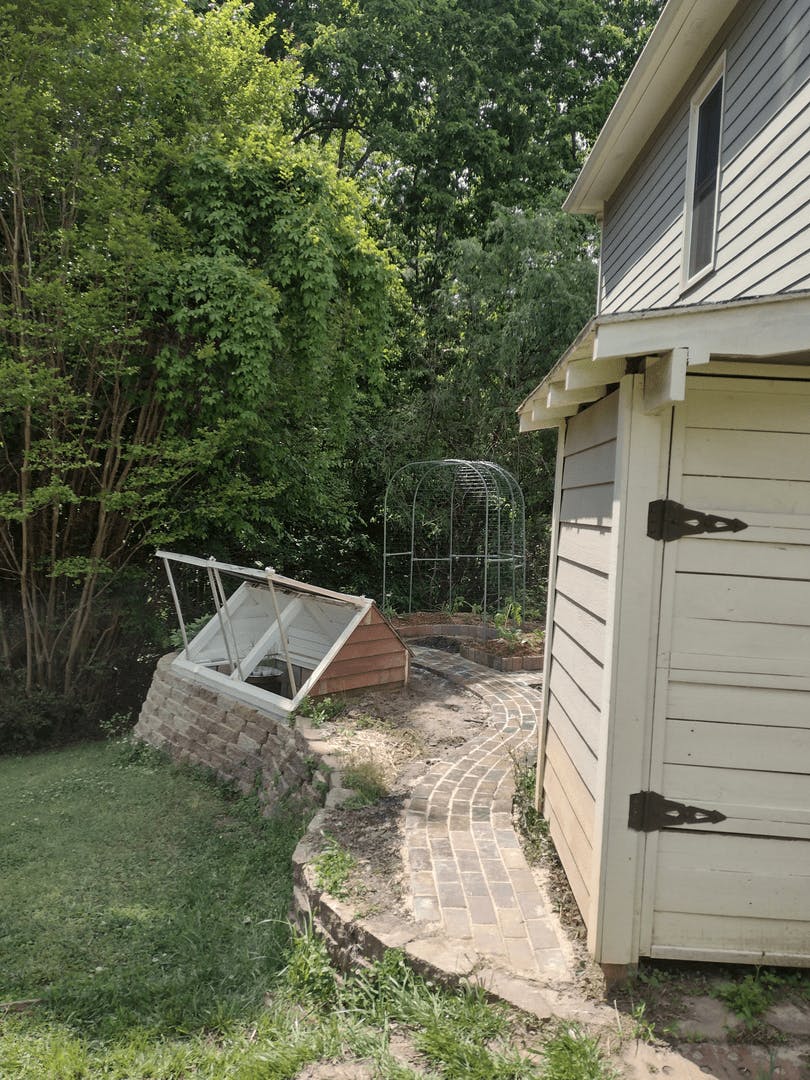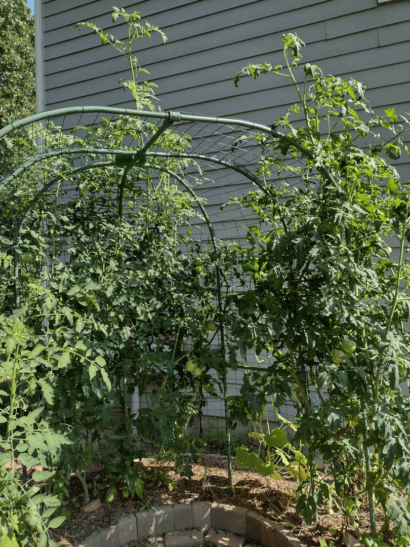
I was finally able to pull the trigger on this trellis. (I had to wait until I built enough of the terrace it sits on.)
There are several hacks in this project I'd like to share.
I used 1/2" EMT for this project because it's cheaper and easier to bend than 3/4" and plenty strong for this application. I have a simple trellis in my garden that's about six years old that's made of 1/2" EMT and has stood through some pretty severe storms (one of which took down a nearby tree). The trellis is anchored to the ground using 1/2 rebar. I cut the rebar into 17" lengths and drove each piece about half way into the ground, then set the trellis legs over the rebar. The raised bed was built around the trellis afterward so that the legs are partially buried as well. It's pretty sturdy.
I wanted the curves in this trellis to be on an 18" radius. To do that with my bender, I needed to make incremental bends. So, I had to do some math. I started by figuring out the circumference of a circle with an 18" radius:
Circumference = 2 x π x radius = 2 x π x 18" = 113" (rounded off)
Since my curves are 90° (1/4 of a circle), I needed to divide by 4:
113" / 4 = 28.25"
So, I needed about 28.25" of EMT to make each curve.
Next, I divided the 28.25" into 9 increments (each to be bent 10°)
28.25" / 9 = 3.14" (rounded off to 3-1/8").
(You may notice that the exact measurement of the incremental distance is equal to π. Don't assume that to be a constant. It only works out that way with an 18" radius when using this technique. If you're making curves with a larger or smaller radius, you will need to calculate the increments for that radius.)
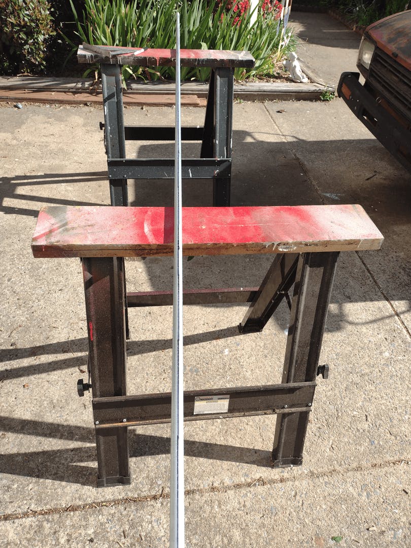
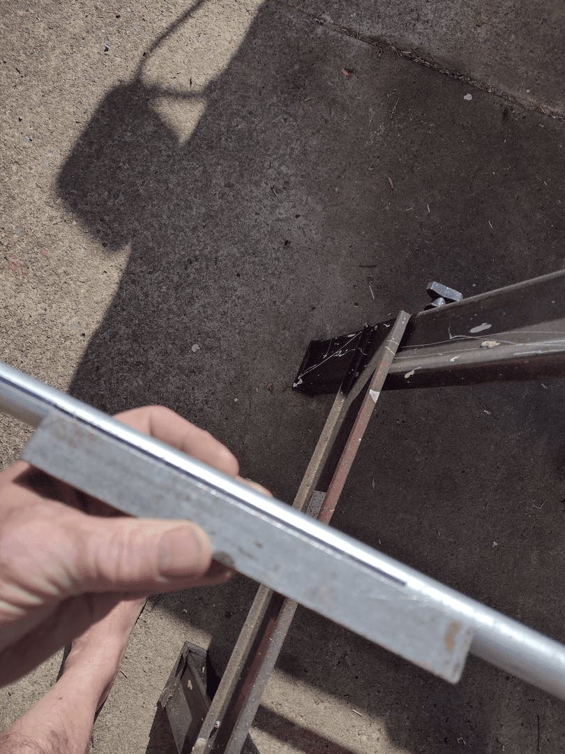
There is a line running lengthwise down the side of the EMT, but it's hard to see. I like to go over it with a sharpie so that it shows up better and I don't lose it in the sun. Here I've used a speed square to make sure my line is straight, but you can use any small piece of angle material, so long as it's true.
Next, I marked the beginning of each of my incremental bends with a sharpie. Here's a tip for marking your material: if you're marking off increments, always mark from the beginning. For instance, I've made my marks at 3-1/8", 6-1/4", 9-3/8", and so on, always measuring from the beginning. That way, if I make a small error in one of my marks, it probably won't show up. But if I made my first mark at 3-1/8", then measured 3-1/8" from that one, and so on, any inaccuracy in my marks would be multiplied and the cumulative error could be quite noticeable.
Also, just a note here on using sharpies to mark your material. Black sharpie can be cleaned off with a mild solvent. Red sharpie is much more permanent and will take a strong solvent and a great deal of elbow grease to remove. And if you try painting over red sharpie, it will usually bleed through. My tip is to stick with black if using a sharpie to mark your material.
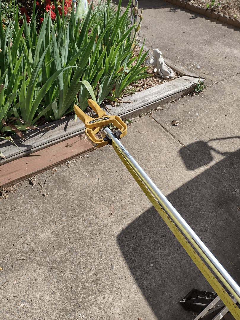
I used a spring clamp to hold the tape measure at the end of the conduit. These are great when you're working alone and two hands aren't enough (and they're relatively inexpensive).
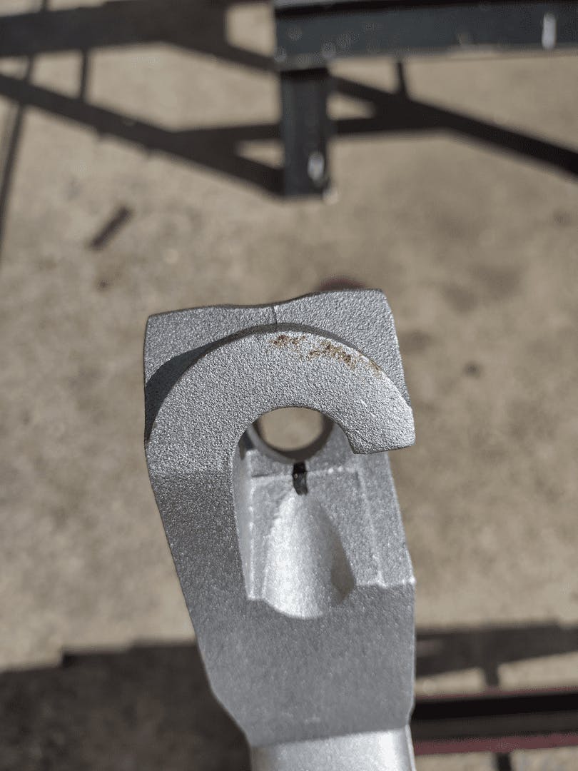
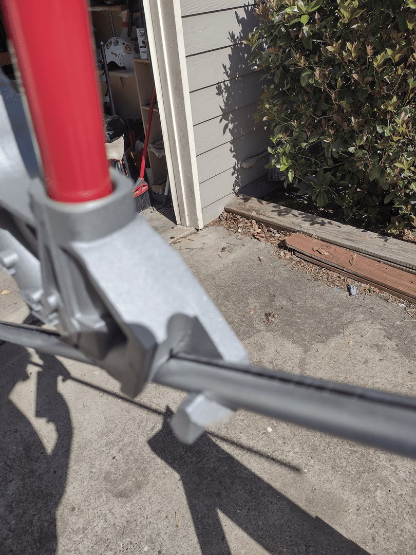
You can see that I've marked the head of my tubing bender to line up with the line running lengthwise on the tubing. This helps to make a true bend.
It's hard to get exactly 10° on each bend. One way to check the overall angle is 90° is to lay one leg of your EMT flat on a known level surface (I used the floor of my garage) and use a level to check the vertical leg. You can bend it by hand until it's right.
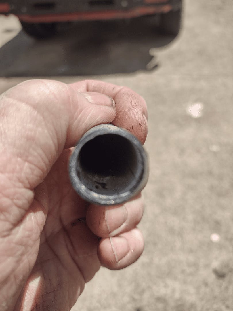
There are several ways to cut EMT. I prefer using a simple, old fashioned tubing cutter. Regardless of how you cut your tubing, some cuts must be completely deburred. Most tubing cutters have an attached deburring tool, which is fine for making the tubing safe (so you won't cut your fingers with it) but it usually won't completely remove the narrowing of the tubing at the end. For this, I like to use a file or my rotary tool with a small sanding drum attachment. Today, I used a rat tail file. Here you can see what the end of the tube looks like after filing. This took me less than two minutes for each cut.
I chose to use standard EMT couplings for the vertical connections on the four front legs rather than MakerPipe 180° connectors. I drew it up both ways in CAD and preferred the aesthetics of the smaller coupling. I plan to build at least one more of these in the future (a larger one) and will probably use the 180° couplings on all 7 legs, attaching the horizontal braces through them and eliminating most of the T's. That will take some more design work, though.
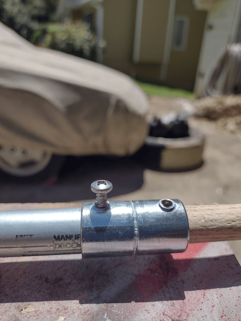
For this project, I reinforced the standard EMT couplings by inserting a piece of 5/8" oak dowel in the tubing and replacing the set screws with wood screws and drilling pilot holes in the EMT and the dowels. The dowels are slightly big for the EMT, so I shaved them down a little with a rasp. It only took about 5 minutes to prep each of the 4 dowels. (These were the cuts I had to debur, in order to fit the dowel into the EMT.)
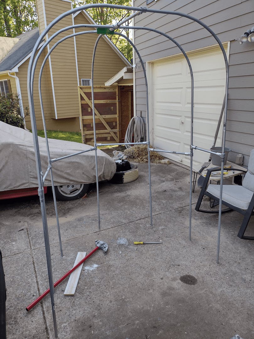
Assembling the frame was a bit of a trick. It all worked in the CAD drawing, so I knew it would all fit together, but it took some patience. I tightened all of the connections just enough to hold together but loose enough to adjust them until I got everything in alignment, then tightened everything up at once.
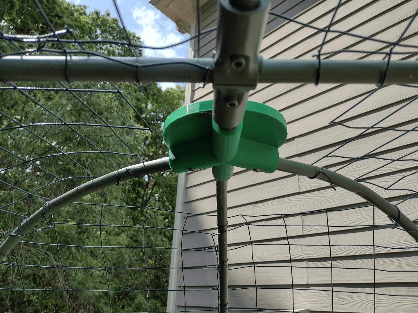
The plastic part at the top where the three rear legs come together was custom made. I designed it and sent a hand-drawn sketch to my son who created the file and printed it on his 3D printer. It's made from ABS plastic which is a bit more resistant to degradation by UV exposure than the more common 3D printer filaments.
When painting EMT (and MakerPipe connectors) I've had pretty good success using Rust-Oleum automotive primer and spray paint.
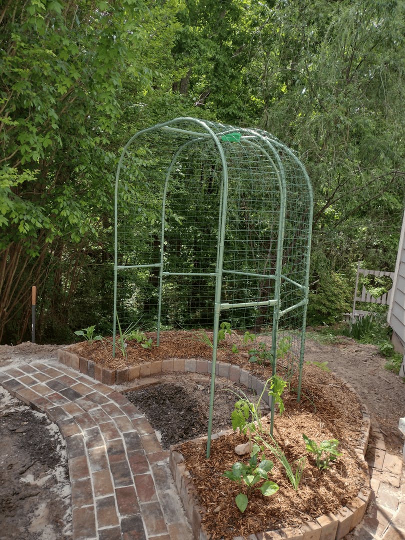
After painting, I covered the trellis with 2"x3" PVC coated welded wire. I started out by attaching it with standard plastic wire ties to hold it in place. The wire ties are strong enough, but they have to be replaced each year because they get brittle and will break. I went back afterward and used thin wire to attach the fencing, then removed the wire ties. The picture here is of attaching the wire to my other trellis (which is not painted). I used some stainless steel mechanics wire for it. (Mechanics wire is like Gorilla tape and a speed square; once you've got it, you can't imagine what life was like before you had it.)
UPDATE:
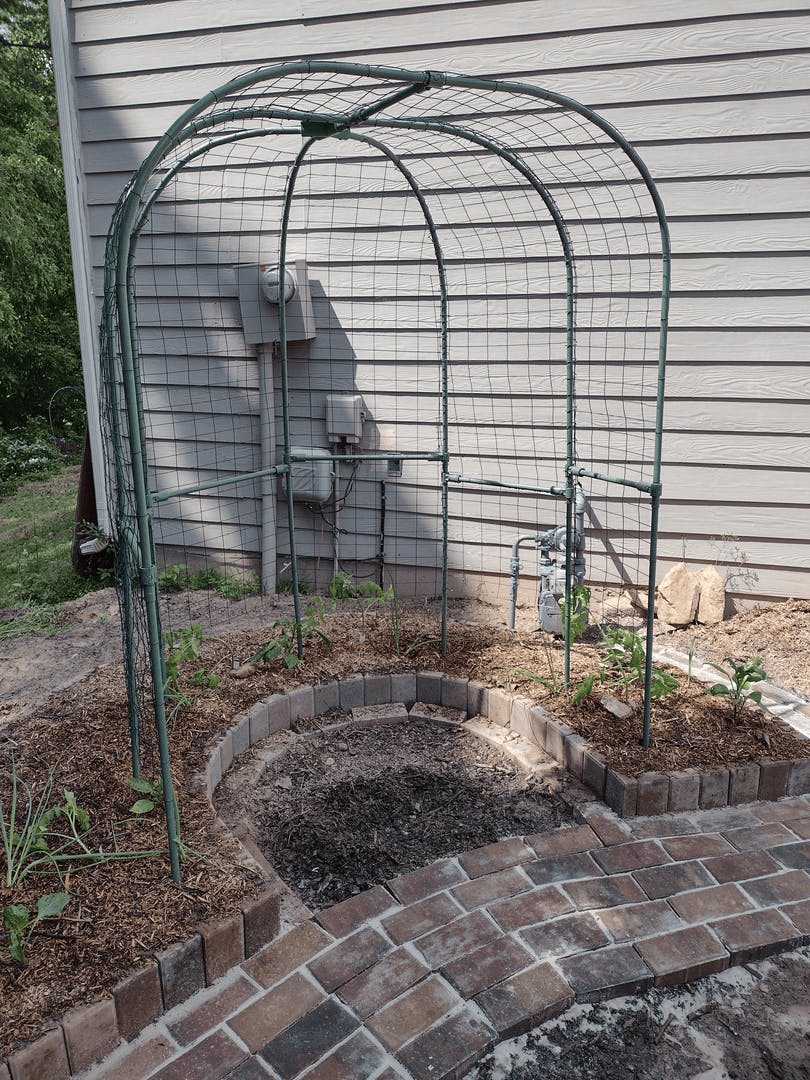
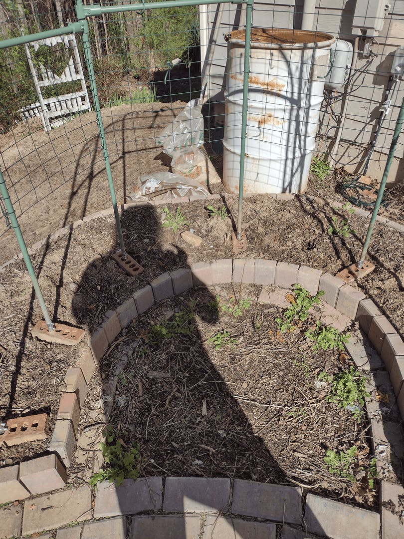
When I originally built this trellis last year, I anchored it to the ground by driving 17" long pieces of 1/2" rebar into the ground at each leg, then just dropped the trellis legs over the rebar. This method is very effective for preventing the trellis from blowing over. Unfortunately, the weight of the tomato plants pushed the trellis deeper into the soft soil - more so on one side than on the other. The result was a very noticeable lean. I came up with a fix that I hope will prevent this in the future.
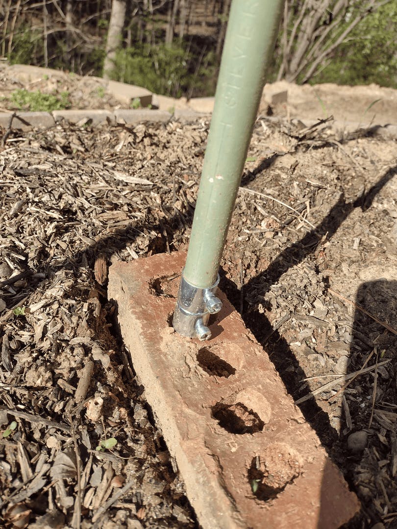
I had some bricks left over from a previous project - the kind with the little holes in them. I removed the trellis and pulled up the rebar stakes, filled the holes they came out of, and re-drove the stakes in the original locations (but not quite so deep). Then I placed a brick over each stake so the rebar extends about 6"-8" above the top of the brick. Then I leveled all the bricks to the same horizontal plane.
At this point, I probably could have set the trellis back on the stakes as before, but since the 1/2" EMT is only barely wider than the holes in the bricks, I found some standard EMT couplings laying around in my garage and placed one on the bottom of each leg. I tightened each top screw to secure it to its associated leg, and tightened the bottom screws down best I could on the rebar.
I've added two no pictures to this post that I hope will make the upgrade clear.